English
 русский
 Español
Content
- 1 What Makes a Condensing Unit the True Core of Refrigeration?
- 2 Key Components & Their Functional Roles
- 3 Critical Performance Metrics You Must Monitor
- 4 How to Select the Right Condensing Unit: A Practical Guide
- 5 Comparison of Condensing Unit Types (Air-Cooled vs. Water-Cooled vs. Evaporative)
- 6 Refrigeration Cycle Flowchart: Where the Condensing Unit Operates
- 7 Proactive Maintenance That Delivers Measurable Gains
- 8 Common Condensing Unit Issues & Corrective Actions
- 9 Frequently Asked Questions (FAQ)
- 9.1 1. How often should I replace a condensing unit?
- 9.2 2. Can I oversize a condensing unit for future expansion?
- 9.3 3. What is the ideal condensing temperature for energy efficiency?
- 9.4 4. Do I need a crankcase heater on my condensing unit?
- 9.5 5. What’s the cost difference between standard and high-efficiency condensing units?
The condensing unit is unequivocally the heart of any refrigeration system — it dictates overall energy efficiency, operational reliability, and system lifespan. Proper selection and maintenance of the condensing unit directly impact total cost of ownership: studies show that optimizing condensing unit performance can improve system efficiency by 25–35% while reducing unplanned downtime by up to 60%. Without a correctly sized and maintained condensing unit, even the best evaporators and controls will fail to deliver consistent cooling.
This guide provides actionable insights into condensing unit anatomy, performance metrics, selection criteria, and proven maintenance strategies — all backed by industry data and free from brand bias.
What Makes a Condensing Unit the True Core of Refrigeration?
A refrigeration system removes heat from a controlled space and rejects it elsewhere. The condensing unit houses two of the four primary components: the compressor (the “pump”) and the condenser coil with its fan (the “heat rejecter”). It accounts for over 75% of the system’s electrical consumption and determines the system’s ability to maintain precise temperatures under varying loads.
Without a reliable condensing unit, refrigerant cannot be pressurized or condensed effectively, leading to evaporator starvation, high suction pressures, and eventual compressor failure. In commercial refrigeration, each 10°F reduction in condensing temperature improves overall system efficiency by 8–12% — a direct reflection of condensing unit design and maintenance.
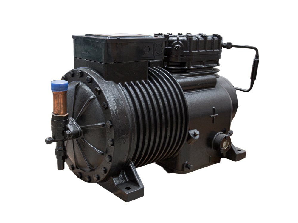
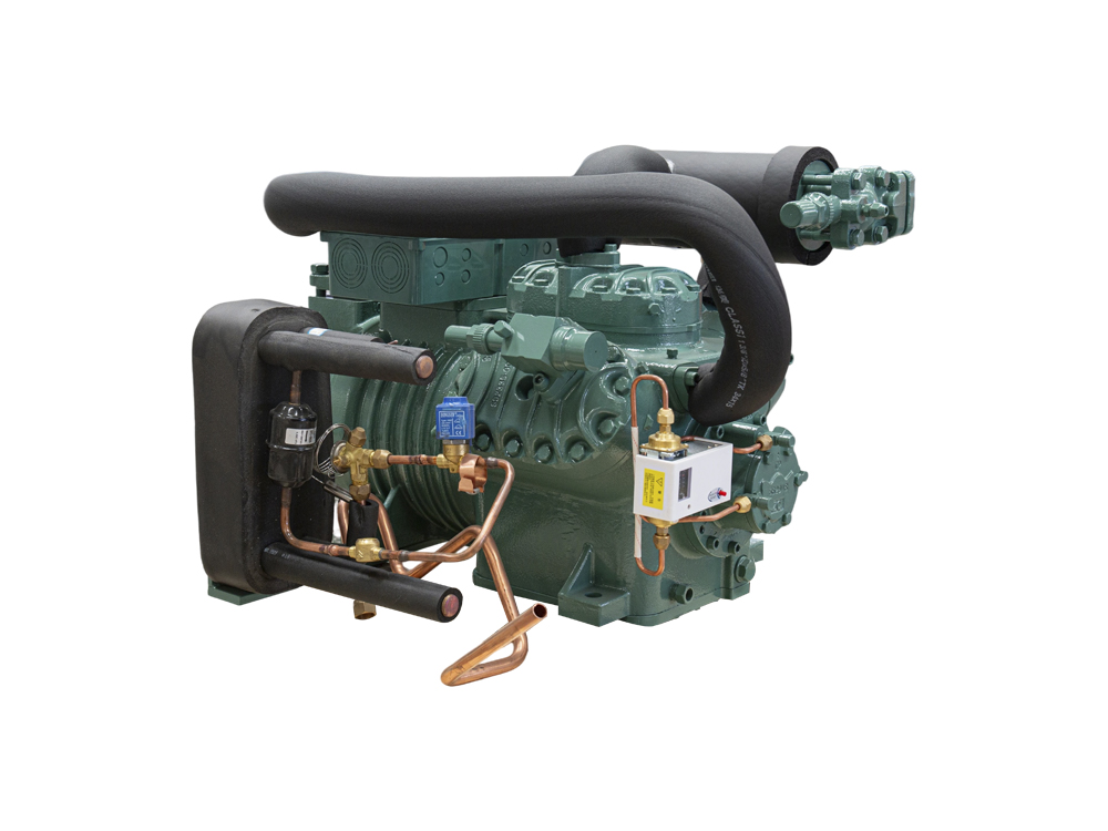
Key Components & Their Functional Roles
Every condensing unit integrates several critical parts. Understanding each helps diagnose issues and optimize performance.
- Compressor – Raises refrigerant pressure and temperature. Reciprocating, scroll, or rotary types; scroll compressors offer 10–15% higher volumetric efficiency in medium-temperature applications.
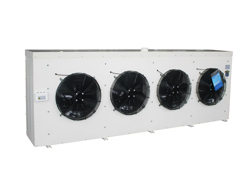
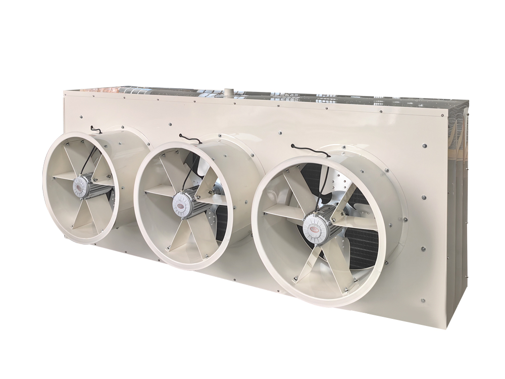
- Condenser Coil (fin-and-tube or microchannel) – Rejects superheat and latent heat. Microchannel coils reduce refrigerant charge by up to 30% while improving heat transfer.
- Condenser Fan (or water pump for water-cooled) – Forced airflow/waterflow removes heat. A 15% drop in airflow reduces heat rejection capacity by 20–25%, directly raising head pressure.
- Receiver (on many units) – Stores liquid refrigerant to match varying system loads, preventing floodback.
- Control & Safety Devices – High/low-pressure switches, fan cycling controls, and crankcase heaters protect the unit from off-cycle migration and extreme conditions.
Critical Performance Metrics You Must Monitor
To evaluate condensing unit health and efficiency, track these quantifiable indicators:
- Condensing Temperature (CT) vs. Ambient/Entering Fluid – For air-cooled units, a CT of 20–30°F above ambient is typical. A spread above 35°F indicates fouled coils or fan issues.
- Compressor Discharge Temperature – Should remain below 225°F (107°C) for most refrigerants to avoid oil breakdown and valve damage.
- Subcooling at Condenser Outlet – Target 5–15°F subcooling. Lower values indicate underfeeding or non-condensables; higher values suggest overcharge or restricted flow.
- Efficiency Ratio (EER / COP) – At full load, modern condensing units achieve EER from 9 to 16 depending on type. A drop of >12% from baseline signals component degradation.
How to Select the Right Condensing Unit: A Practical Guide
Selection directly affects energy bills and reliability. Use these four steps:
- Step 1 – Match capacity to evaporator load – Calculate total BTU/hr at design evaporating temperature. Oversizing by >20% causes short cycling and low oil return.
- Step 2 – Define ambient conditions – For air-cooled units, use maximum expected ambient (e.g., 110°F/43°C) to avoid high-pressure cutouts. For water-cooled, use entering water temperature and fouling factor.
- Step 3 – Choose refrigerant – Low-GWP options like R-449A or R-513A have comparable capacity to R-404A with 65% lower GWP, but may require adjustment in liquid line components.
- Step 4 – Select regulation method – EEV (electronic expansion valve) paired with a condensing unit allows 15–25% part-load efficiency improvement over traditional thermostatic expansion valves.
Comparison of Condensing Unit Types (Air-Cooled vs. Water-Cooled vs. Evaporative)
Each type serves specific applications. The table below summarizes key characteristics without brand references.
| Type | Cooling Medium | Typical EER Range | Best Application |
|---|---|---|---|
| Air-Cooled | Ambient air | 9 – 12 | Small to medium walk-ins, remote supermarkets (dry climates) |
| Water-Cooled | City or cooling tower water | 12 – 16 | Large industrial processes, high ambient heat islands |
| Evaporative-Cooled | Air + water evaporation | 15 – 20 | Hot, dry climates; ammonia systems; large central plants |
Data note: Evaporative condensers can lower condensing temperature by 15–25°F compared to air-cooled at 95°F ambient, reducing compressor energy by up to 18%. However, they require water treatment to avoid scaling.
Refrigeration Cycle Flowchart: Where the Condensing Unit Operates
The condensing unit encompasses the compression and condensation stages. Below is a simplified visual flow of the entire vapor-compression cycle.
- Compressor
- →
- Condenser Coil
- →
- Expansion Device
- →
- Evaporator
- →
- Back to Compressor
Within the condensing unit: The compressor discharges high-pressure superheated gas into the condenser where it rejects heat and becomes a high-pressure liquid (subcooled). This liquid is then supplied to the expansion valve and evaporator. A clean, well-performing condenser ensures minimal subcooling loss and stable system operation.
Proactive Maintenance That Delivers Measurable Gains
Neglected condensing units lose efficiency rapidly. Field data shows that coil fouling increases energy consumption by 15–20% in just six months. Implement this evidence-based schedule:
- Monthly: Inspect condenser fans for vibration/amps; clean coil surfaces with low-pressure water or compressed air. A 0.1-inch water column pressure drop increase reduces heat transfer by 8%.
- Quarterly: Check refrigerant charge via subcooling and superheat. Undercharge of 10% can lower capacity by 15% while overcharge raises head pressure 20–30 psi above normal.
- Annually: Analyse compressor oil (acidity, moisture). Oil with TAN > 0.5 mg KOH/g signals imminent failure; replace oil filters if present.
- Biannual (water-cooled): Descaling condenser tubes. A 1/16-inch scale layer reduces heat transfer coefficient by up to 40%, directly lifting condensing pressure.
Common Condensing Unit Issues & Corrective Actions
Even robust units experience failures. Recognizing symptoms early prevents catastrophic downtime.
- High Head Pressure (>30°F above normal CT) – Causes: dirty condenser, fan motor failure, non-condensables. Action: clean coil, test fan capacitor, purge air from system.
- Short Cycling Compressor – Causes: low pressure switch due to refrigerant leak, or oversized unit. Action: locate leak, recalculate load; adjust deadband if applicable.
- Liquid Floodback to Compressor – Causes: oversized evaporator, wrong TEV superheat setting. Action: adjust superheat to 8–12°F at compressor suction; install suction accumulator.
- Excessive Noise/Vibration – Causes: worn compressor springs, loose mounting bolts, or liquid slugging. Action: measure vibration displacement; replace isolators; check oil level.
Proactive tip: Installing a real-time monitoring system that tracks discharge pressure and temperature can predict 80% of compressor failures up to two weeks in advance.
Frequently Asked Questions (FAQ)
1. How often should I replace a condensing unit?
With proper maintenance, a condensing unit typically lasts 15–20 years. Consider replacement when repair costs exceed 50% of a new unit’s price or efficiency drops by >25% from original ratings.
2. Can I oversize a condensing unit for future expansion?
Oversizing beyond 15% of actual load causes short cycling, poor oil return, and humidity control issues. Use multiple smaller units or a variable-speed condensing unit for turndown capability.
3. What is the ideal condensing temperature for energy efficiency?
For every 10°F reduction in condensing temperature, system COP improves roughly 8–10%. However, too low condensing (below 80°F for many compressors) risks liquid migration. A practical setpoint is 95–105°F for air-cooled under moderate ambient.
4. Do I need a crankcase heater on my condensing unit?
Yes for outdoor installations or where the compressor is colder than the evaporator. A crankcase heater prevents refrigerant migration and liquid slugging during start-up, reducing compressor failure risk by 40% in cold climates.
5. What’s the cost difference between standard and high-efficiency condensing units?
Although this article avoids specific pricing, industry benchmarks indicate that high-efficiency units (EER >13) typically command a 20–30% premium but pay back in 2–4 years due to energy savings, especially in 24/7 operations.