

 English
 русский
 Español
Content
- 1 What an Air-Cooled Condensing Unit Actually Contains
- 2 Why Air-Cooled Rejection Suits Most Cold Room Projects
- 3 How to Size an Air-Cooled Condensing Unit
- 4 Configuration Choices That Decide Long-Term Performance
- 5 Installation and Site Conditions That Decide Reliability
- 6 Commissioning, Maintenance and Fault Patterns
- 7 Specification Mistakes That Cost Money Later
- 8 Frequently Asked Questions
- 8.0.1 Q1: What is the difference between an air-cooled condensing unit and an air-cooled condenser?
- 8.0.2 Q2: How do I choose between an open type, a box type and a split type unit?
- 8.0.3 Q3: What ambient temperature should I design for?
- 8.0.4 Q4: Can an air-cooled condensing unit operate in winter?
- 8.0.5 Q5: Which configuration details matter most in a corrosive environment?
- 8.0.6 Q6: How often does an air-cooled condensing unit need maintenance?
An air-cooled condensing unit is rarely the largest line item in a cold room budget, yet it is the component most often blamed when a room drifts above its set point. The unit sits between the load inside the room and the weather outside the building, so any mismatch between its rated capacity and the real operating point shows up as pressure, heat and electricity rather than as a tidy specification error.
This guide covers the engineering decisions that decide whether an air-cooled condensing unit behaves as expected on a hot afternoon in July and on a cold morning in January. It explains what the package contains, how to size it against a real load, how configuration choices change long-term performance, and which installation and maintenance habits separate a twelve-year machine from a three-year one.
What an Air-Cooled Condensing Unit Actually Contains
An air-cooled condensing unit is a factory-assembled package that moves heat out of a refrigeration circuit and into the surrounding air. Inside the housing sit a compressor, an air-cooled condenser coil, one or more axial fans, a liquid receiver and the control panel that starts, stops and protects the assembly. The unit ends at the liquid line connection; everything from the expansion device to the evaporator belongs to the cold room side of the system.
The wording causes confusion, because the same phrase describes a bare condenser coil in power generation and process cooling. In commercial and industrial refrigeration, an air-cooled condensing unit always means the compressor plus condenser package, quoted in horsepower or in kilowatts of heat rejection, and supplied with refrigerant connections, a mounting frame and a control panel.
| Component | Primary function | What it governs |
|---|---|---|
| Compressor | Raises refrigerant pressure and temperature | Capacity, current draw, number of stages |
| Condenser coil | Transfers heat from hot gas to ambient air | Condensing temperature, discharge pressure, subcooling |
| Axial fan and motor | Moves air across the finned surface | Heat rejection, sound level, low ambient behaviour |
| Liquid receiver | Stores liquid refrigerant | Stable feed to the expansion device, charge tolerance |
| Control panel | Switching, fan cycling, safety cut-outs | Restart behaviour, fault diagnosis, protection |
| Housing and frame | Directs airflow and carries components | Service access, corrosion life, wind loading |
The circuit below traces the path of the refrigerant and shows where the boundary of the unit sits. Hot gas leaves the compressor, condenses inside the coil while ambient air carries the heat away, liquid collects in the receiver, the expansion device drops the pressure, and the evaporator inside the cold room absorbs heat before suction gas returns to the compressor.
Why Air-Cooled Rejection Suits Most Cold Room Projects
Air-cooled units dominate distributed refrigeration for practical reasons. They need no cooling tower, no water treatment programme and no permanent water supply, so the owner avoids pumps, basins, blowdown and the chemistry that keeps a water circuit clean. They arrive as a single package, which shortens site work, and they can be placed close to the room they serve, keeping refrigerant pipework short and pressure losses low.
The trade-off is sensitivity to ambient air. Capacity falls and power consumption rises as the ambient climbs, so a unit that looks comfortable in spring can become marginal in August. The table compares the three common heat rejection routes on the criteria that usually settle the decision.
| Criteria | Air-cooled | Water-cooled | Evaporative |
|---|---|---|---|
| Heat rejection medium | Ambient air | Circulating water and tower | Air plus water evaporation |
| Water consumption | None | High through tower losses | Moderate but continuous |
| Ambient sensitivity | High | Low | Medium |
| Installation scope | Packaged unit only | Unit, tower, pumps and piping | Unit plus water supply |
| Routine maintenance | Coil cleaning, fan bearings | Water chemistry, pumps, tower | Water distribution, scale control |
| Typical best fit | Distributed cold rooms and retrofits | Large plants with water infrastructure | Dry climates with reliable water |
How to Size an Air-Cooled Condensing Unit
A condensing unit is chosen to reject the load that the evaporator absorbs plus the heat the compressor adds, so the calculation starts with the room and ends with the compressor envelope. Working in the other direction, from a catalogue page towards a room, is the most common source of underperforming installations.
- Build the load. Add transmission, product pull-down, door infiltration, defrost allowance, fan and lighting heat, and personnel activity, then apply a design margin of ten to fifteen percent for the uncertainties every project carries.
- Set the evaporating temperature. Storage rooms are normally designed with a temperature difference of six to ten kelvin between room air and evaporating refrigerant; blast freezing and process cooling need values chosen around the product.
- Set the condensing temperature. Ambient plus ten to fifteen kelvin is standard practice. A larger coil that allows a smaller approach costs more up front and saves energy every hour afterwards.
- Correct the published capacity, because catalogue ratings assume a nominal ambient, typically between thirty and thirty-eight degrees Celsius, and a clean coil with unrestricted airflow.
- Confirm the compressor envelope at the worst condition the site will ever see, then check how the unit behaves at part load, since it will spend most of its life there.
A capacity correction table turns a catalogue number into a site number. The factors below are typical for air-cooled condensing units with clean coils and unrestricted airflow; they must be replaced by the manufacturer figures for the specific model under review.
| Design ambient, degrees Celsius | Capacity factor | Operator note |
|---|---|---|
| 25 | 1.08 to 1.12 | Fan cycling or speed control may be needed |
| 30 | 1.03 to 1.06 | Close to the nominal catalogue point |
| 35 | 1.00 | Reference point used by many catalogues |
| 40 | 0.92 to 0.95 | Check compressor current against nameplate |
| 45 | 0.85 to 0.89 | Verify the envelope and all protection settings |
Altitude has a smaller but real effect, because air density falls roughly one percent per hundred metres above sea level and heat rejection follows it. A site at fifteen hundred metres can lose four to six percent of rated capacity, which is enough to erase a thin safety margin. Recirculation of warm discharge air does the same damage in a different way, and it is far more common than altitude. A unit pushed against a wall, or facing another unit across a narrow gap, can lose ten percent or more of its effective capacity without any change to the catalogue rating.
For a worked example, take a frozen storage room with a calculated load of twenty-two kilowatts, evaporating at minus twenty-five degrees Celsius and condensing at forty-five degrees Celsius during a thirty-five degree ambient. After correction, the unit must deliver more than twenty-two kilowatts at that operating point plus the design margin. A unit chosen from the nominal rating alone falls roughly ten percent short on the hottest days, and the room takes longer to recover after every door opening.
Configuration Choices That Decide Long-Term Performance
Two units with identical nominal capacity can behave very differently after five years. The differences come from materials, fan arrangements, housing geometry and the way the controls handle part load and low ambient conditions.
Coil, Fin and Tube Materials
The coil decides how the unit survives its environment. Aluminium fin and aluminium tube packs suit dry, clean locations and general cold room work. Copper tube with aluminium or copper fins transfers heat more readily and tolerates humid air better. Stainless steel tube and fin construction answers washdown areas, food plants and aggressive industrial atmospheres, where a premium is paid for service life rather than for efficiency. Coating choices follow the same logic: hydrophilic foil helps condensate drain from the coil, while corrosion-resistant foil coatings and electrophoretic treatments extend life near coastlines and chemical plants.
Fan and Motor Arrangement
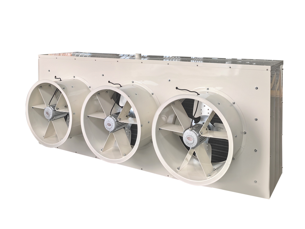
Axial fans with external rotor motors dominate because they are compact and easy to replace. Internal rotor motors on separate brackets appear where higher static pressure, longer duct runs or extra protection from water ingress matters. The number of fans changes how capacity steps down: a four-fan unit can drop one fan in cold weather and keep the rest running, while a single-fan unit must cycle the whole condenser. Speed-controlled motors give finer control and lower night-time noise, at the cost of a controller that has to be set up correctly at commissioning.
Housing, Airflow Path and Format
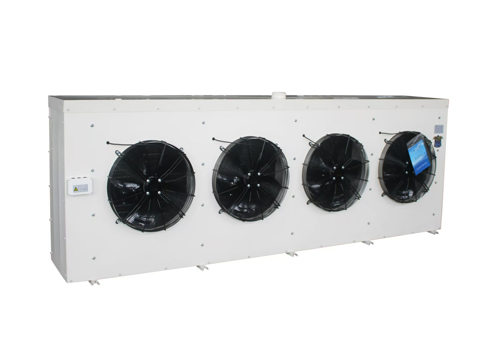
Housings range from flat plate types, where air enters from one or two faces and leaves horizontally, to box bodies that draw air from several sides and pack more coil area into a small footprint. Split designs separate the coil from the compressor so heat can be rejected remotely, which suits plant rooms, noise-sensitive boundaries and roofs with limited load capacity. Stainless steel housings and ducted air outlets exist for food plants and washdown zones. Whatever the format, the airflow path has to be planned so that warm discharge air cannot return to the coil face.
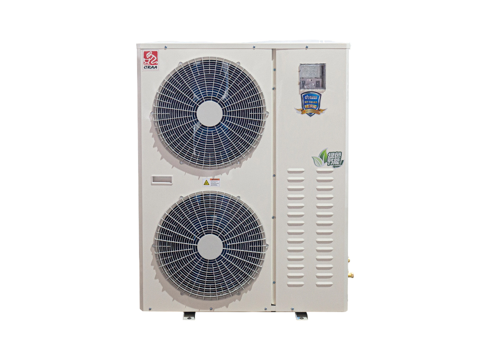 5P All-in-One Condensing Unit for Commercial RefrigerationPackaged compressor, condenser, receiver, expansion valve and electronic controls support small to medium cold storage, display cases, process equipment and commercial air conditioning.View Product →
Projects with unusual airflow, corrosion or footprint requirements rarely fit a standard catalogue description. They are built around a drawing instead, which is why such work usually goes to a supplier with in-house design and manufacturing rather than to a distributor working from a list.
Controls, Defrost and Electrical Layout
Integrated control panels keep wiring short and simplify service. Some packages carry the electrical box above the compressor, others beside it, and the position decides how much room a technician has to work. Low ambient control, fan cycling, pressure differential control for ultra-low temperature storage and defrost logic that cooperates with the evaporator all belong on the specification list, not on the list of items to fix after handover.
Installation and Site Conditions That Decide Reliability
Site conditions are part of the selection, not an afterthought. A correctly sized unit in a badly chosen position will run hot, cycle on its high pressure switch and consume more energy than a smaller machine with a clean air path.
- Leave a clear air path. Warm air leaving the unit should travel away from the coil face and away from walls, parapets and nearby equipment.
- Avoid recirculation. Two units facing each other, or a unit set hard against a wall, can pull its own discharge air back across the coil.
- Respect wind and sun. Direct afternoon sun on the coil and a prevailing wind that pushes discharge air back towards the unit both raise condensing temperature.
- Allow service space. Coil cleaning, fan replacement and panel access need room, and a unit squeezed into a gap will be neglected until it fails.
- Handle vibration and noise. Anti-vibration mounts and correctly supported pipework prevent cracked lines, and sound limits near residential boundaries may push the unit to a roof or a remote position.
- Match the evaporator. The temperature difference, the airflow pattern of the air cooler and the defrost method selected for the air cooler must suit the same operating point as the condensing unit.
Piping between the unit and the room deserves the same attention. Liquid lines that are undersized or exposed to hot roof surfaces lose subcooling and flash before the expansion valve. Long suction runs need traps and correctly sized lines to bring oil back to the compressor. Insulation that is thin, wet or missing is a quiet, permanent drain on capacity.
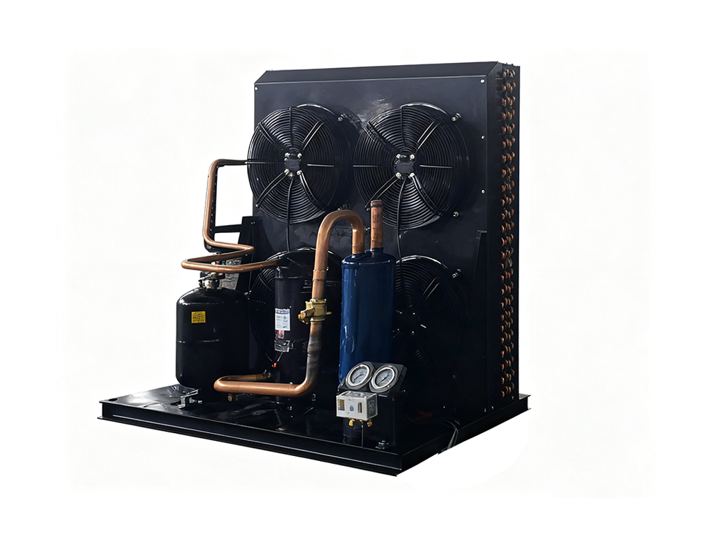 8HP Open Packing Condensing Unit for Industrial RefrigerationOpen 8HP compressor, air-cooled condenser, receiver and pressure controls suit medium- and low-temperature commercial or industrial refrigeration; accessible layout aids maintenance and system integration.View Product →
Commissioning, Maintenance and Fault Patterns
Commissioning is where a design becomes a working plant or becomes a service call. Record the ambient temperature, the discharge and suction pressures, superheat and subcooling, the compressor current against nameplate, fan operation, control settings and every safety cut-out value. Those numbers turn later troubleshooting from guesswork into comparison.
Routine maintenance is short and repetitive: clean the coil, check fan blades and bearings, verify contactor condition, look for oil traces at joints, confirm the receiver level and test the safety devices. The table below maps the complaints that arrive most often onto the checks that resolve them.
| Symptom | Most likely cause | First check |
|---|---|---|
| High discharge pressure | Dirty coil, recirculation, overcharge, non-condensable gas, fan failure | Coil face and fan rotation |
| Low suction with normal discharge | Restricted expansion valve, blocked filter drier, low charge | Superheat and sight glass |
| Repeated trips on high pressure | Ambient above the design point, condenser undersized for the site | Ambient reading and capacity factor |
| Repeated fan motor failure | Voltage imbalance, moisture in the terminal box, wrong rotation | Supply voltage and terminal box condition |
| Ice build-up in winter | Low ambient operation without fan speed or pressure control | Low ambient control settings |
Specification Mistakes That Cost Money Later
Most failures on site trace back to a handful of decisions taken early, when the quotation was still being compared on price alone.
- Selecting on nominal capacity without correcting for the site ambient and altitude.
- Using compressor displacement as a substitute for capacity at the real operating point.
- Cutting coil area to reduce first cost, which raises discharge pressure for the life of the plant.
- Ignoring part-load behaviour, so the unit short-cycles through spring and autumn.
- Choosing materials for the catalogue price rather than for the site atmosphere.
- Forgetting service access, which turns a fifteen-minute coil clean into a two-hour job and therefore rarely happens.
Frequently Asked Questions
Q1: What is the difference between an air-cooled condensing unit and an air-cooled condenser?
An air-cooled condenser is only the heat exchanger that turns hot gas back into liquid. An air-cooled condensing unit contains that condenser plus the compressor, the fan assembly, the receiver and the control panel, which means it can be piped to an evaporator and commissioned as a complete high side of the system.
Q2: How do I choose between an open type, a box type and a split type unit?
Open types expose the compressor and coil on a frame, which gives the best service access and suits plant rooms. Box types enclose the components so air is drawn from several faces, concentrating more coil area into less space. Split types separate the coil from the compressor, allowing the condenser to sit outdoors while the compressor stays indoors, which helps with noise limits, cold weather starting and roof loading.
Q3: What ambient temperature should I design for?
Work from a local summer design temperature that is exceeded only for a small number of hours each year, then confirm the compressor can still run at the absolute maximum the site will see with protection in place. Designing around an average summer day leaves the plant short during the one week when it matters most.
Q4: Can an air-cooled condensing unit operate in winter?
Yes, but the controls must be able to reduce heat rejection. Fan cycling, fan speed control or a pressure regulating valve keeps discharge pressure high enough for the expansion device and for compressor lubrication. Without low ambient control the unit short-cycles, loses subcooling and wears out contactors.
Q5: Which configuration details matter most in a corrosive environment?
Tube and fin material, housing material and any coating applied to the coil decide how long a unit survives a coastal site, a food plant washdown bay or a chemical store. Stainless steel construction and corrosion-resistant foil coatings cost more at purchase and usually cost far less per year of service.
Q6: How often does an air-cooled condensing unit need maintenance?
Coil cleaning, fan and bearing inspection, contactor checks and a leak survey are normally scheduled two to four times a year, with more frequent cleaning where air carries dust, flour, fat or salt. The work itself is short, and the cost of skipping it is a higher condensing temperature every day until the coil is finally cleaned.
A condensing unit is a small part of a refrigeration budget and a large part of its operating cost. Matching it to the real load, the real ambient and the real site takes an hour at the design stage and saves far more than that once the room is in service, loaded with product and unable to hold its set point.


 Contact Number:+86-18858565929
